
HEA sections table
In this page the properties of the European HE-A steel sections are tabulated (also known as IPBl). HE-A profiles are wide-flange, double-tees with parallel flanges.
Table configuration: |
Design Code: | |||
Steel: | |||
E = | |||
fy = |
 |
HEA properties table | |
Units: |
| Profile | Dimensions | Weight | Geometry | Detailing | Major Axis | Minor Axis | Shear | Torsion/Warping | ||||||||||||||||||||
|---|---|---|---|---|---|---|---|---|---|---|---|---|---|---|---|---|---|---|---|---|---|---|---|---|---|---|---|---|
| Surface Area | Surface Area | |||||||||||||||||||||||||||
(*) is provided only for Eurocode 3 (2022) class 3 sections |
HEA strength and classification table | |||
Units: | |||
| Profile | Major Axis Bending | Minor Axis Bending | Classification for local buckling | ||||||||
|---|---|---|---|---|---|---|---|---|---|---|---|
| Moment | Shear | Moment | Shear | Flexure-Major | Flexure-Minor | Compression | |||||
| - | - | - | |||||||||
(**) Class 4 sections or shear buckling calculations for Eurocode 3 are not yet supported |
List of symbols | |
: | the overall height of the section |
: | the overall width of the section (=width of the flanges) |
: | the flange thickness |
: | the web thickness |
: | the radius of the fillet |
: | weight of the section (per length) |
: | area of the cross-section |
: | perimeter of the cross-section |
: | the parallel length of the web (net distance between flanges minus the fillets) |
: | distance between flanges (including the fillets) |
: | parallel length of the half-flange (fillet excluded) |
: | cantilever length of the half-flange (fillet included) |
: | moment of inertia (2nd moment of area) around major axis (y) or minor axis (z), respectively |
: | section modulus (elastic) around major axis (y) or minor axis (z), respectively |
: | plastic section modulus around major axis (y) or minor axis (z), respectively |
: | elasto-plastic section modulus [2] around major axis (y) or minor axis (z), respectively |
: | radius of gyration (i.e ) around major axis (y) or minor axis (z), respectively |
: | shear area of the section for load parallel to web (axis z) |
: | shear area of the section for load parallel to flanges (axis y) |
: | torsional constant |
: | warping constant |
: | elastic moment (the moment causing the edge fibers to yield) |
: | plastic moment (moment for fully plastified section) |
Statistical information | |||
Here, a visualization of some key properties of the HEA sections are given as a function of either sectional height or sectional weight . | |||
Steel: | |||
Design Code: | |||
ADVERTISEMENT
Formulas
Table of contents
Geometrical properties
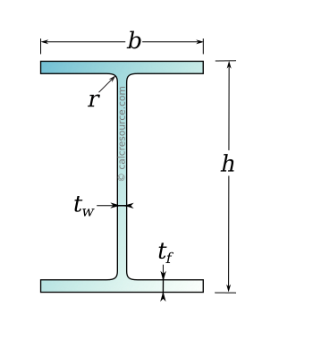
HE-A sections are European, wide-flange, double-tee profiles with parallel flange edges. Their dimensions are standardized in EURONORM 53-62, using the following five properties:
- the height of the section
- the width of the flanges
- the web thickness
- the flange thickness
- the fillet radius
These definitions are shown in the following figure.
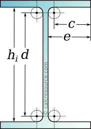
Other geometrical properties can be derived from the five basic dimensions. For instance, the following properties provide some measurements of the section that can be useful for detailing purposes:
- the clear distance between flanges
- the straight segment of the web
- the length from the flange edge to the web
- the straight segment of the flange (one half of it)
These are illustrated in the following figure:
The section area and the perimeter of any HE-A section can be formulated as:
- Area:
- Perimeter:
Weight
The weight of any beam with a section that doesn't change along its length (aka prismatic beam) is determined by the section area and the density of the material. Considering carbon steel, which has a density equal to 7850 kg/m3 (or equivalently 0.2836 lbf/in3), the weight per length of a HEA beam, with section area , is found as:
- (the result in kg/m)
or:
- (the result in kg/m)
or:
- (the result in lbf/in)
Mechanical properties
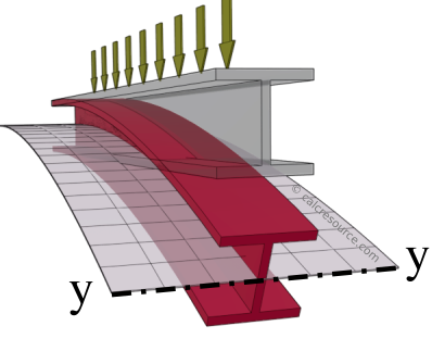
Loading parallel to web
Mechanical properties related to the transverse loading of a beam are necessarily defined around an axis of bending. This in term, depends on the direction of loading. Loading parallel to the web results in bending around axis y, also called major axis. Accordingly, all mechanical properties related to bending around y, are marked with index y. Such a case is illustrated in the following drawing.
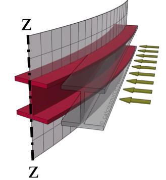
Loading parallel to flanges
Loading parallel to the flanges results in bending around axis z, also called minor axis. Accordingly, all mechanical properties related to bending around z, are marked with index z. Such a case is illustrated in the following drawing.
Moment of inertia
The moment of inertia (second moment or area) is used in beam theory to describe the rigidity of a beam against flexure. For a HEA section, it can be calculated with the following formulas, for loading parallel to web (i.e. bending around y) or parallel to flanges (i.e. bending around z), respectively:
Radius of gyration
The radius of gyration is property that describes how far from the axis the area of the section is distributed. It is given by the following two formulas, for the major axis (y) and minor axis (z), respectively:
Section modulus
The section modulus of a section is typically used for the calculation of its strength in bending, assuming linear elastic conditions (for this reason also called elastic section modulus). It is directly related to the moment of inertia. For a symmetric section around the axis of bending - (HEA is symmetric around both major and minor axis), it can be calculated with the next two formulas, for loading parallel to web (i.e. bending around y) or parallel to flanges (i.e. bending around z), respectively:
Plastic section modulus
The plastic modulus of a section is typically used for the calculation of its strength in bending, assuming fully plastic conditions. For a HEA section, it can be calculated with the following formulas, the first one for loading parallel to web (i.e. bending around y) and the second for loading parallel to flanges (i.e. bending around z), respectively:
Shear area
The shear area of a section is typically used for the calculation its strength against shear. For loading parallel to the web, shear area is roughly the area of the web (different approximations are given in building codes):
- , according to Eurocode 3 (2005, 2022). Conservatively, can be 1.
- , according to ANSI/AISC 360-16 (2016):
For loading parallel to the flanges, shear area is the combined area of the two flanges:
Torsional loading
HEA sections are open sections and under torsional moments they develop both St Venant torsion and warping.
Torsion constant
The torsion constant is related to the rigidity of the section under St. Venant torsion. Closed formed solutions are not available however, and its calculation is typically performed either through numerical methods or using empirical expressions. Here, the formula in Kraus & Kindmann (2009) is adopted:
where:
Warping constant
The warping constant for HEA sections is calculated by the formula:
References
Euronorm 53-62 (1962), Breedflensbalken met parallele flenzen; Publications Office of the European Union.
AISC (2016), Specification for structural steel buildings ANSI/AISC 360-16; American Institute of Steel Construction: Chicago, USA
Eurocode 3, EN1993-1, (2005), Design of steel structures - Part 1-1: General Rules and Rules for Buildings; CEN, Brussels, Belgium.
Eurocode 3, EN1993-1, (2022), Design of steel structures - Part 1-1: General Rules and Rules for Buildings; CEN, Brussels, Belgium.
Kraus, M., & Kindmann, R. (2009). St. Venants Torsion Constant of Hot Rolled Steel Profiles and Position of the Shear Centre. In Proceedings of 11th Nordic Steel Construction Conference (NSCC), Malmö, Sweden (pp. 454-461).