
Moment of Inertia of a Zeta (Z)
This tool calculates the moment of inertia I (second moment of area) of a zeta section (Z-section). Enter the shape dimensions h, b, tf and tw below, taking into account the provided drawing. The calculated results will have the same units as your input. Please use consistent units for all input.
h = | |||
b = | |||
tf = | |||
tw = | |||
Results: | |||


ADVERTISEMENT
Theoretical background
Table of contents
Axis parallel to flanges
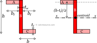
The moment of inertia of a z-section can be found if the total area is divided into three, smaller ones, A, B and C as shown in figure below. Sub-area B accounts for the entire web (including the two small areas where flanges and web interesect), while sub-areas A and C account for the remaining flange parts, (A for the upper flange and C for the lower one). Sub-areas B, C are identical in terms of sectional area, each having a width equal to . The wanted moment of area of the entire z-section, around a specific neutral axis, can be considered as the additive combination of , of the individual moments of the sub-areas, over the same axis. It is perfectly possible to split the given z-section in many different ways. However, the end result should be the same if the methodology is followed consistently. It is important however that the individual moments of inertia , , , have to be determined around the same axis, before such a summation can be made. See our article on finding the moment of inertia of compound shapes for more details on the methodology.
Let's consider here, the moment of inertia around the centroidal axis x, of the z-section, which is parallel to the two flanges. This axis happens to also be centroidal for the rectangular sub-area B, however the same is not true for sub-areas A and C. Therefore, the parallel axes theorem should be employed for these two sub-areas (later in text, a short introduction on the parallel axes theorem is given). Indeed, centroidal axis x, lies at a distance equal to from the parallel axis through the sub-area A centroid (and the same distance from sub-area C centroid too).
As a result, the moments of inertia of the each sub-area A, B and C around the axis x are:
where .
Notice, that the formulas for and are identical, since both sub-areas have identical shape and also the same distance from x axis. The summation of the above three moments of inertia gives us the moment of inertia of the whole section, around axis x. Here is the result, after a little bit of algebraic manipulation:
where , the flange width, the web thickness, the flange thickness and the section height.
Axis parallel to web
The same methodology can be followed for the determination of the moment of inertia around an axis parallel to the z-section web. We will use the same areas A,B and C, though this is not mandatory. As mentioned before, the resulting moment of inertia should be the same, even if we choose another way to subdivide the sectional area.
The centroidal axis y, of the z-section, which is parallel to the web, happens to also be centroidal for sub-area B. Therefore the parallel axes theorem is not required for this sub-area. This is not the case for sub-areas A and C. Indeed, centroidal axis y, lies at a distance from the parallel axis passing through sub-area centroid (the same for A and C).

As a result, the moments of inertia of the each sub-area A, B and C around the axis y become:
where .
Notice, that the formulas for and are identical, since both sub-areas have identical shape and also the same distance from y axis. The summation of the above three moments of inertia gives us the moment of inertia of the whole section, around axis y. Here is the result, after a little bit of algebraic manipulation:
where , the flange width, the web thickness, the flange thickness and the section height.
Product of inertia
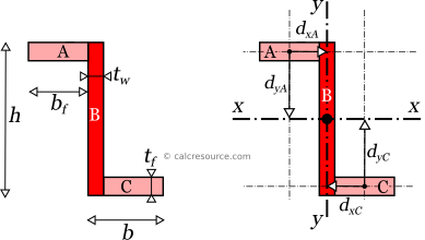
The product of inertia of a Z-section can also be easily determined using the sub-areas A, B and C. For each sub-area the product of inertia is zero (around axes parallel to x and y, passing through the respective sub-area centroids). This is due to their rectangular shape, which is symmetrical. The product of inertia around an axis of symmetry is always zero. Thus, we only have to consider the parallel axis effect for each sub-area. Distances of sub-area centroids from the sectional centroid are depicted in the following figure and determined next:
for sub-area A:
for sub-area B:
for sub-area C:
Next, we apply the parallel axes theorem, for the products of inertia of each sub-area, around the centroidal axes x and y:
The summation of the above gives us the product of inertia of the whole section, around axes x and y:
or:
Parallel non centroidal axes
Having found the moments of inertia around the centroidal axes x and y, it is rather easy to determine the moment of inertia around any axis, parallel to either x or y. We just have to know the distance of the parallel axis from the centroidal one. The so-called Parallel Axes Theorem can then be used to determine the wanted moment of inertia. In its general form, the theorem is expressed as:
where I' is the moment of inertia around the wanted axis, I the moment of inertia around the centroidal axis, parallel to the first one, d the distance between the two parallel axes and A the area of the shape. In the case of the Z-section the area is :
where .
For example, in order to find the Z-section moment inertia around an axis x0, passing from the the top flange edge (parallel to x), we first determine the distance between the two parallel axes: that is .
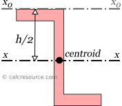
Applying, the parallel axes theorem we find:
Simply, replacing the expressions for and we get:
And after some refactoring we get:
where
Product of inertia in parallel axes
For the product of inertia , the parallel axes theorem takes a similar form:
where is the product of inertia around centroidal axes x, y, and is the product of inertia, around axes that are respectively parallel to x, y and also distanced by and from them.
Rotated axes
For the transformation of the moments of inertia from a system of axes x,y to another one u,v, that is rotated by an angle , the following equations are used:
where , the moments of inertia about the initial axes and the product of inertia. , and are the respective quantities for the rotated axes u and v.
Principal axes
In principal axes, that are rotated by an angle relative to original centroidal ones x,y, the product of inertia becomes zero. Because of this, any symmetry axis of the shape, is also a principal axis. The moments of inertia about principal axes, are called principal moments of inertia, and the respective axes, principal axes. It occurs that among all possible rotations of the x,y axes, the principal axes (typically named I and II) produce the maximum and minimum values for the moments of inertia.
If , and are known for the arbitrary centroidal coordinate system x,y, then the principal moments of inertia and the rotation angle θ of the principal axes can be found, through the next expressions:
Dimensions
The dimensions of moment of inertia (second moment of area) are .
Mass moment of inertia
In Physics the term moment of inertia has a different meaning. It is related with the mass distribution of an object (or multiple objects) about an axis. This is different from the definition usually given in Engineering disciplines (also in this page) as a property of the area of a shape, commonly a cross-section, about the axis. The term second moment of area seems more accurate in this regard.
Applications
The moment of inertia (second moment or area) is used in beam theory to describe the rigidity of a beam against flexure (see beam bending theory). The bending moment M applied to a cross-section is related with its moment of inertia with the following equation:
where E is the Young's modulus, a property of the material, and κ the curvature of the beam due to the applied load. Beam curvature κ describes the extent of flexure in the beam and can be expressed in terms of beam deflection w(x) along longitudinal beam axis x, as: . Therefore, it can be seen from the former equation, that when a certain bending moment M is applied to a beam cross-section, the developed curvature is reversely proportional to the moment of inertia I. Integrating curvatures over beam length, the deflection, at some point along x-axis, should also be reversely proportional to I.