
Moment of Inertia of composite shapes
Table of contents
Procedure outline
The given analytical formulas for the calculation of moments of inertia usually cover, just a handful of rather simple cases. The possible shape geometries one may encounter however, are unlimited, but most of the times, these complex areas can be decomposed to more simple subareas. In this article, it is demonstrated how to calculate the moment of inertia of complex shapes, using the Parallel Axes Theorem.
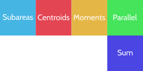
In general, the steps for the calculation of the moment of inertia of a composite area, around an axis (called global axis hereafter), are summarized to the following:
- Identify simply shaped subareas the composite area can be decomposed to.
- Determine the distance from global axis of the centroid of each one of the subareas.
- Determine the moment of inertia of each subarea, around a parallel axis, passing through subarea centroid.
- Apply the Parallel Axes Theorem to find the moment of inertia of each subarea around the global axis.
- Add (or subtract for negative subareas, see examples) the moments of inertia from the last step.
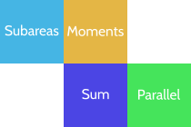
With step 1 we aim to divide the complex area under investigation to smaller and more manageable subareas. While doing so, we must ensure that we can efficiently obtain the moment inertia of each subarea, around a parallel axis. Efficiency is important, because sometimes there are many ways to decompose an area, but not all of them are equally easy for calculations. The following picture demonstrates a case of a composite area, that is decomposed to smaller subareas, using three different methods (among many others possible). The global axis of rotation is indicated with red dashed line. With method 'a', the number of subareas is 4, with method 'b' it is 5 and and with method 'c', 6.
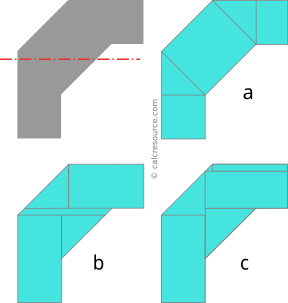
Method 'a' seems more simple, and employs the least number of subareas, but the calculation of the moment of inertia of the central inclined rectangle is rather hard. No formula is available for this particular angle of inclination of the rectangle that gives its moment of inertia around an axis parallel to the global one. Firstly, we have to find the moments of inertia Ix and Iy around the inclined centroidal axes of the rectangle, and then transform them around a horizontal axis, using the formulas for axis rotation. Surely, it can be done this way, but it is not very efficient calculation wise. Methods 'b' and 'c' on the other hand, do not present such a problem. For each one of their subareas, there are easily available analytical formulas, we can use to calculate their moments of inertia around a parallel to global axis. In particular, method 'b' seems a bit more efficient, since it employs one less subarea, compared to method 'c'.
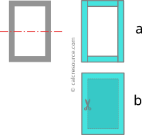
Sometimes, it is more efficient to define negative subareas, that when subtracted from another, bigger subarea, produce the total composite shape. Take as an example the rectangular tube in the next figure. Conventionally, it can be decomposed to 4 rectangular subareas, one for each of the walls, that added together produce the composite shape (method 'a'). But a more efficient method is to define just two rectangular subareas, one for the outer perimeter and one for the inner perimeter (method 'b'). The latter, if subtracted from the former, produces the composite shape and for this reason is characterized as negative subarea. Following this pattern, the moment of inertia of the negative subarea is going to be subtracted from the respective one of the outer perimeter, in order to find the resulting moment of inertia of the rectangular tube. Apart from this, all other steps of the calculation procedure are normally applicable for the negative subarea.
With step 2, we determine the centroid of each subarea, specifically its distance from the global axis. The work we have to do in this step, depends on the way the subareas have been defined, in the first step. Simpler subareas, generally require less calculations to find their centroid, but also the position of subarea, relative to the global axis is important. Visiting again the rectangular tube (Figure 3), if the global axis is a centroidal one (passing through middle height of the section), then using method 'b', the centroids of the two rectangular subareas, are located on middle height too, and therefore feature zero distance from the global axis. To the contrary, with method 'a', the centroids of top and bottom subareas feature non-zero distance from global axis, which we have to find. Consequently, going with method 'b', not only we avoid any calculation, but as an additional benefit, the work we must do for step 4 (Parallel Axis Theorem) should be less.
With step 3, we calculate the moment of inertia of each subarea around the parallel axis passing through its centroid. Normally, we use available formulas (tables with moments of inertia of common shapes can be handy, check this one) but if none is available, we have to calculate the definite integral, , over the whole subarea, where variable y is the distance from the axis. Again, the definition of the subareas in step 1, heavily affects the work we have to do here.
With step 4, we apply the Theorem of Parallel Axes to all subareas, so that their moments of inertia, get all transferred around the global axis:
where, Ai is the surface area of subarea i, di is the distance of subarea i centroid from the global axis (as determined in step 2), Ii,c is the moment of inertia of subarea i around its centroid (as determined in step 3) and Ii,g is the wanted moment of inertia of subarea i around the global axis.
With step 5, we add all the resulting moments of inertia from previous step and the final sum is the wanted moment of inertia of the composite area around global axis. If we have any negative subareas defined though, we have to subtract them from the sum. Using a mathematical expression:
where index i indicates a normal (positive) subarea, while index j indicates a negative one.
Note that addition (or subtraction) of the moments of inertia, Ii,g , of the multiple subareas, is allowed in this step because all of them are defined around the same axis of rotation, the global one. That was indeed the purpose of step 4. To the contrary, we are not allowed to do the same with the moments of inertia from step 3, because each one is defined around a different parallel axis, passing through the local subarea centroid.
When all subareas share a convenient common axis
In some cases, it occurs so that all defined subareas share a common axis of rotation that is convenient to calculate their moments of inertia around. By convenient, it is meant that a) it is parallel to the global axis and b) there are available and easy to calculate formulas for all subareas. It is not necessary a centroidal axis neither identical to the global axis.
In such cases, it may be preferable to calculate the moments of inertia of the subareas around this convenient axis. The required steps, with this simplified procedure are outlined like this:
- Identify simply shaped subareas the composite area can be decomposed to.
- Calculate the moment of inertia of each subarea around the convenient axis.
- Add (or subtract for negative subareas, see examples) the moments of inertia from the last step.
- Apply the Theorem of Parallel Axes to find the moment of inertia of the composite shape, around the global axis
With step 3, the moment of inertia of the composite area is found around convenient axis O-O:
where index i indicates a normal (positive) subarea, while index j indicates a negative one.
Addition (or subtraction) of the moments of inertia of multiple subareas is allowed because all of them have been found in step 2 around the same axis, the convenient one.
With step 4, the moment of inertia of the composite area gets transferred, using the Theorem of Parallel Axes, from the convenient axis, to the global axis:
where dg is the distance of global axis from the composite area centroid, do is the distance of convenient axis from the composite area centroid, and A is the surface area of composite shape. Of course, if these two axes, convenient and global, are coincident then this step is redundant and we simply conclude that: . Also, if the global axis is a centroidal one, then the above expression is simplified to: .
Example 1
Calculate the moment of inertia of the shape shown in the following figure, around a horizontal axis x-x, passing through centroid. Shape dimensions are: b=15'', h1=20'', h2=10''.
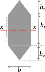
Due to symmetry, the centroid of the composite area is located in the middle height of the shape, that is also the middle of height h1. Since global axis x-x (in red color) is passing through centroid, it passes through the middle of h1too.
Step 1
We divide the composite area to smaller subareas as shown in the following schematic. Three subareas are defined, one rectangular and two triangular. These will be referred as, subareas 1,2 and 3, as depicted in the figure.
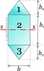
No convenient axis of rotation exists, common to all three subareas. We will continue with the remaining steps of the procedure (see Figure 1).
Step 2
For each subarea, we find the distance of its centroid from the global axis. As described in the beginning, the global axis is passing through the middle of h1.
For subarea 1, that is a triangle with height h2, the centroid is located, , above the base of the triangle. Therefore, its distance from the global axis is:
For subarea 2, that is a rectangle, the centroid is located at the middle of its height , which coincides with the location of the global axis. Therefore:
For subarea 3, we don't need to make any calculation, since, due to symmetry, it must have the same distance from global axis, with subarea 1. That is:
The negative sign indicates a position below the axis. Note that the sign of distance is not important, since by definition, it gets squared, and as a result, subareas at either sides of the axis, contribute positively to the moment of inertia.
Step 3
For each subarea, we find the moment of inertia around a parallel to x axis passing through subarea centroid. We use available formulas from this table.
For subarea 1:
For subarea 2:
For subarea 3, no calculation is needed, because its shape is identical to that of subarea 1. Therefore:
Step 4
For each subarea we apply the Theorem of Parallel Axes, to find its moment of inertia around global axis x-x. We use the distances, , from step 2, and the moments of inertia, , from step 3. We need the surface area of each subarea too, so we find them first:
Now we apply the Theorem of Parallel Axes, for each subarea.
For subarea 1:
For subarea 2:
For subarea 3:
Due to symmetry around the global axis, the result for subarea 3 should not be different than that of subarea 1:
Step 5
We add for all subareas, the moments of inertia from the last step:
This is the wanted moment of inertia of the composite area, around axis x-x.
The following table organizes the calculation procedure in a tabular format:
| Area | Ic | d | A | Ix=Ic+Ad2 |
|---|---|---|---|---|
| (in4) | (in) | (in2) | (in4) | |
| 1 | 416.67 | 13.333 | 75 | 13750 |
| 2 | 10000 | 0 | 300 | 10000 |
| 3 | 416.67 | -13.333 | 75 | 13750 |
| Total | 450 | 37500 |
Example 2
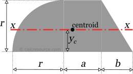
Calculate the moment of inertia of the shape given in the following figure, around a horizontal axis x-x that is passing through centroid. Shape dimensions are: r=20'', a=15'', b=12''. The curved edge is a circular one. Also, for the needs of this example, the distance of the centroid from the base of the shape is given: yc=8.8083'' .
Step 1
We divide the composite area to smaller subareas as shown in the following figure. Three subareas are defined, one quarter circle, one rectangle and one right triangle. These will be referred as, subareas 1,2 and 3, as depicted in the figure.
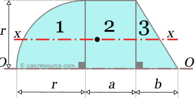
Looking closely to the three subareas, we can recognize that there exists a common, parallel to x, axis around which all three moments of inertia can be easily found: the axis passing form the base of the shape. We name it axis O, and from here on, we will follow the simpler procedure, which is applicable only when a convenient common axis exists for all subareas (see Figure 4).
Step 2
For each subarea, we find the moment of inertia around the convenient axis O, passing through the base. We use available formulas from this table.
For the quarter circular subarea 1:
For the subarea 2:
For the subarea 3:
Step 3
We add the moments of inertia around the convenient axis O, for all subareas:
Step 4
For the total composite area, we apply the Theorem of Parallel Axes, to find its moment of inertia around the global axis x-x. We need the surface area of the composite shape, so we will find it first, through the already defined subareas 1,2 and 3.
Subarea 1: .
Subarea 2: .
Subarea 3: .
Total area:
Next, the moment of inertia of the composite area around axis O (from step 3) gets transferred, using the Theorem of Parallel Axes, to global axis x, which happens to be a centroidal one too. The theorem takes the form:
where yc is the distance of the centroid from the base, in other words the distance between the two axes. In our case it is given, so we may proceed directly to the calculation:
This is the wanted moment of inertia of the composite area around axis x-x.
Example 3
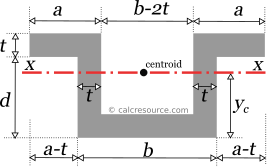
Calculate the moment of inertia of the shape given in the following figure, around a horizontal axis x-x that is passing through centroid. Shape dimensions are: a=25'', b=50'', d=30'' and t=9''. For the needs of this example, the distance of the centroid from the base of the shape is also given: yc=19.5''
Step 1
The total area is divided to smaller subareas as depicted in the next figure. Four subareas are defined, all of them rectangular. Subareas 2,3 and 4 are negative ones, and are subtracted from subarea 1, which surrounds the shape from left to right and from bottom to top.
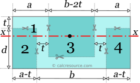
No convenient axis of rotation is identified, that facilitates the calculation of the moments of inertia commonly for all subareas. The standard procedure will be followed in the next steps (as outlined in Figure 1).
Step 2
For each subarea, we find the distance of its centroid from the global axis. The distance of the global axis from the base is yc and it is given. We have to find the distance of each subarea centroid from base, and subtract it from yc. The difference shall be the distance between subarea centroid and the global axis.
Subarea 1, is a rectangle with height d+t, and its centroid is located at the middle of this height. Therefore, its distance from the global axis is:
Subarea 2, is a rectangle, with height d. Therefore:
The negative sign indicates that the centroid lies below the global axis.
Subarea 3, is also a rectangle, with height d, but with an offset t from base. Thus the distance of its centroid from global axis should be:
For subarea 4, we don't need to make a new calculation, since it is similar to subarea 2. Thus:
Step 3
In this step, the moment of inertia of each subarea is calculated, around a parallel to x axis, passing through its centroid.
For the rectangle of subarea 1, the width is: , and the height is: . The moment of inertia is:
Subareas 2 and 4, both have width: , and height: , the moment of inertia is found:
And finally, for subarea 3, the width is: , and the height is: . Its moment of inertia is:
It would be wrong to add or subtract the moments of inertia we just have found, because each one is related to a different axis of rotation, passing through the centroid of the respective subarea.
Step 4
In this step, the Theorem of Parallel Axes is applied, for each subarea, in order to find its moment of inertia around the global axis x-x, knowing its moment of inertia around its centroid. The distances, , from step 2, and the moments of inertia, , from step 3 will be utilized. However, the surface areas are also needed. Without writing again the dimensions of each subarea, from the previous step, the surface areas are found:
Now we apply the Theorem of Parallel Axes, for each subarea.
For subarea 1:
For subarea 2:
For subarea 3:
For subarea 4:
No calculation is needed, due to similarity with subarea 2:
Step 5
In this step the resulting moments of inertia from the previous step are added together. We are entitled to add or subtract them now, because all have been found around the same axis, the global one. The negative subareas 2,3 and 4, should be subtracted from the sum.
This final answer for the moment of inertia of the composite area around centroidal axis x-x.
The above calculation procedure can be summarized in a table, like the one shown here:
| Area | Ic | d | A | Ix=Ic+Ad2 |
|---|---|---|---|---|
| (in4) | (in) | (in2) | (in4) | |
| 1 | 405347 | 0 | 3198 | 405347 |
| 2 (negative) | 36000 | -4.5 | 480 | -45720 |
| 3 (negative) | 72000 | 4.5 | 960 | -91440 |
| 4 (negative) | 36000 | -4.5 | 480 | -45720 |
| Total | 5118 | 222467 |