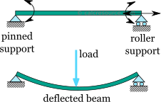
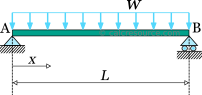
The simply supported beam is one of the most simple structures. It features only two supports, one at each end. A pinned support and a roller support. With this configuration, the beam is allowed to rotate at its two ends but any vertical movement there is inhibited. Due to the roller support it is also allowed to expand or contract axially, although free horizontal movement is prevented by the other support. This is a determinant (also called critical) structure, which means that if any of the supports is removed or an internal hinge is inserted, the beam is unable to carry loads anymore and it becomes a mechanism (a structure that moves freely under loading).
Reference table: maximum deflection of simply supported beams
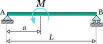
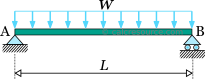
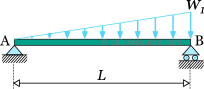
For reference purposes, the following table presents formulas for the ultimate deflection of a simply supported beam, under some common load cases. In all cases, is the material modulus of elasticity and the cross section moment of inertia around the elastic neutral axis. Also, take in mind that a positive sign of the maximum deflection means a downward direction.
Table 1Ultimate deflection of simply supported beam under common load cases
where
where,
where,
Classical beam theory
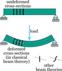
Trying to estimate the deformations of a beam under transverse loading several beam theories are available. The most widely adopted is the Euler-Bernoulli beam theory, also called classical beam theory. The two basic assumptions of the theory are:
the deformations remain small
the cross sections of the beam under deformation, remain normal to the deflected axis (aka elastic curve).
The second assumption is practically valid for beams with homogeneous and isotropic material, with symmetrical cross-section, and with length significantly larger than their cross section dimensions (10 times or more is a common rule of thumb). Effectively, if the the beam deforms significantly in any other form except symmetric bending then the assumption of normal and plane cross sections is not satisfied. Examples of such cases include short beams, beams with sandwich type cross-sections, or slender cross-sections or open unsymmetrical cross-sections.
Also the following assumptions are typically associated with the classical beam theory:
the material is linear elastic
the beam is prismatic, which means that the cross-section remains constant throughout its length
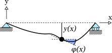
Under these assumptions, the classical beam theory results to the following relationship between the deflection , as a function of and the bending moment :
where, is the modulus of elasticity and the moment of inertia of the cross section.
Finding deflections and slopes
Depending on the material, a beam may develop large deflections without breaking, even remaining elastic. So it can be safe from failure, but there other reasons to consider excessive deflections undesirable. These include comfort of the users, traffic safety (for a bridge), damage to non-structural elements etc. Therefore, finding the deflections is an important step in the static analysis of a structure.
Provided, the bending moment diagram has been determined at a previous stage of the static analysis, and that the classical beam theory is adopted, the differential equation , can be used as a means to find the deflections and the slopes across the beam. If we integrate once, we find the first derivative of the deflection, which represents the beam slope:
Integrating one more time the deflections are found:
The direct integration method is effective only for simple cases. Other methodologies to calculate the deflections include:
Moment area method
Conjugate beam method
Castigliano's method
Virtual work principle
Examples
In this section some examples will be given for the estimation of simply supported beam deflections and slopes, using the direct integration method. This method requires the calculation beforehand of the bending moment diagram. In the context of the examples this will be given, however, if you need to deal with this subject too, please take a look at our relevant article here.
The steps of the methodology are repeated here as they have been described earlier in the text.
Example 1: deflections of a simply supported beam with uniform distributed load (udf), using direct integration
Find the deflections of a simply supported beam, with uniform distributed load, as a function of distance from end A. The beam beam material is elastic with modulus of elasticity and its cross section have a moment of inertia , constant throughout length .
Determine the maximum deflection.
1. Finding deflection and slope expressions as functions of
We will use the direct integration method. We have to find the expression of the bending moments of the same beam against . It turns out to be:
First we find the slopes:
Constant remains unknown for the moment. Next we integrate once more, in order to find the expression of deflections against :
There are two constants that have to be determined. In order to do so, we must introduce the boundary conditions of the problem. There exist two locations, where the deflections are actually known. At the two supports, the deflection is actually zero. For the support at end A, , therefore the following condition should be satisfied:
For the support at end B, , therefore the following condition should be satisfied:
Substituting the constants and , to the slope and deflection expressions, we finally find:
and
2. Finding maximum deflection
The maximum deflection should occur at a point where the first derivative of becomes zero. The first derivative is the slope , that is already found. From there one could set and find the roots.
There are three real roots in the last equation:
However, only the first one is acceptable. The other two lie outside the span of the beam. So, the ultimate deflection occurs at , and can be found by evaluating the at this point:
The physical meaning of the negative sign is that the maximum deflection occurs in the downward direction.
Example 2
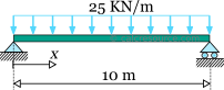
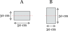
Find the ultimate deflection of the simply supported beam, under uniform distributed load, that is depicted in the schematic. Its cross-section can be either A or B, shown in the figure below. Both cross-sections feature the same dimensions, but they differ in orientation of the axis of bending (neutral axis shown with dashed red line). The modulus of elasticity is 30GPa.
We will use the expression for the ultimate deflection, found in the previous example, for this particular case. It is:
Apart for the moment of inertia , all other parameters are independent of cross-section, so they are common for both cases A and B in this example. Specifically, their values are:
1. Ultimate deflection for cross-section A
The cross-section is rectangular, therefore its moment of inertia around the centroidal neutral axis is given by the formula:
where the cross-section height and the cross-section width. With word 'height' it is meant the dimension perpendicular to the axis of bending while with 'width' we mean the parallel dimension. In this case it is:
Therefore:
All the required parameters for the calculation of ultimate deflection have now been determined. We finally get:
2. Ultimate deflection for cross-section B
With this orientation the height and width of the cross-section are switched. Specifically: