
Moment of Inertia of Triangle
If you are interested in the mass moment of inertia of a triangle, please use this calculator. The current page is about the cross-sectional moment of inertia (also called 2nd moment of area).
This tool calculates the moment of inertia I (second moment of area) of a triangle. Enter the shape dimensions 'b' and 'h' below. The calculated results will have the same units as your input. Please use consistent units for any input.
b = | |||
h = | |||
Results | |||


.")
ADVERTISEMENT
Definitions
The moment of inertia of a triangle with respect to an axis passing through its centroid, parallel to its base, is given by the following expression:
where b is the base width, and specifically the triangle side parallel to the axis, and h is the triangle height (perpendicular to the axis and the base).
The moment of inertia of a triangle with respect to an axis passing through its base, is given by the following expression:
This can be proved by application of the Parallel Axes Theorem (see below) considering that triangle centroid is located at a distance equal to h/3 from base.
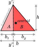
The moment of inertia of a triangle with respect to an axis perpendicular to its base, can be found, considering that axis y'-y' in the figure below, divides the original triangle into two right ones, A and B. These triangles, have common base equal to h, and heights b1 and b2 respectively. Thus their combined moment of inertia is:
Taking into account that and that centroidal parallel axis y-y is at a distance from y'-y' makes possible to find the moment of inertia Iy, using the Parallel Axes Theorem (see below). After algebraic manipulation the final expression is:
Parallel Axes Theorem
The moment of inertia of any shape, in respect to an arbitrary, non centroidal axis, can be found if its moment of inertia in respect to a centroidal axis, parallel to the first one, is known. The so-called Parallel Axes Theorem is given by the following equation:
where I' is the moment of inertia in respect to an arbitrary axis, I the moment of inertia in respect to a centroidal axis, parallel to the first one, d the distance between the two parallel axes and A the area of the shape (=bh/2 in case of a triangle).
For the product of inertia Ixy, the parallel axes theorem takes a similar form:
where Ixy is the product of inertia, relative to centroidal axes x,y, and Ixy' is the product of inertia, relative to axes that are parallel to centroidal x,y ones, having offsets from them and respectively.
Rotated axes
For the transformation of the moments of inertia from one system of axes x,y to another one u,v, rotated by an angle φ, the following equations are used:
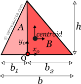
where Ix, Iy the moments of inertia about the initial axes and Ixy the product of inertia. Iu, Iv and Iuv are the respective quantities for the rotated axes u,v. The product of inertia for a triangle is generally nonzero, unless symmetry exists. It can be found, considering the two right triangles A,B in the figure below. Their combined product of inertia relative to axes x0,y0 is:
Taking into account that point 0 distances from centroid are and , the product of inertia Ixy relative to centroid can be found, using the Parallel Axes Theorem.
A general purpose calculator for the transformation of the moments of inertia and the product of inertia, of any 2D shape, due to axis rotation, is available here.
Principal axes
In principal axes, that are rotated by an angle θ relative to original centroidal ones x,y, the product of inertia becomes zero. Because of this, any symmetry axis of the shape, is also a principal axis. The moments of inertia about principal axes, are called principal moments of inertia, and are the maximum and minimum ones, for any angle of rotation of the coordinate system. If Ix, Iy and Ixy are known for the arbitrary centroidal coordinate system x,y, then the principal moments of inertia and the rotation angle θ of the principal axes can be found, through the next expressions:
You can calculate the principal moments of inertia, using our relevant calculator, available here.
Dimensions
The dimensions of moment of inertia (second moment of area) are .
Mass moment of inertia
In Physics the term moment of inertia has a different meaning. It is related with the mass distribution of an object (or multiple objects) about an axis. This is different from the definition usually given in Engineering disciplines (also in this page) as a property of the area of a shape, commonly a cross-section, about the axis. The term second moment of area seems more accurate in this regard.
Applications
The moment of inertia (second moment or area) is used in beam theory to describe the rigidity of a beam against flexure (see beam bending theory). The bending moment M applied to a cross-section is related with its moment of inertia with the following equation:
where E is the Young's modulus, a property of the material, and κ the curvature of the beam due to the applied load. Beam curvature κ describes the extent of flexure in the beam and can be expressed in terms of beam deflection w(x) along longitudinal beam axis x, as: . Therefore, it can be seen from the former equation, that when a certain bending moment M is applied to a beam cross-section, the developed curvature is reversely proportional to the moment of inertia I. Integrating curvatures over beam length, the deflection, at some point along x-axis, should also be reversely proportional to I.