Simply supported beam diagrams
Table of contents
Introduction
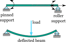
The simply supported beam is one of the most simple structures. It features only two supports, one at each end. One is a pinned support and the other is a roller support. With this configuration, the beam is inhibited from any vertical movement at both ends whereas it is allowed to rotate freely. Due to the roller support it is also allowed to expand or contract axially, though free horizontal movement is prevented by the other support.
Removing any of the supports inserting an internal hinge, would render the simply supported beam to a mechanism, that is body the moves without restriction in one or more directions. Obviously this is unwanted for a load carrying structure. Therefore, the simply supported beam offers no redundancy in terms of supports, and if a local failure occurs the whole structure would collapse. These type of structures that offer no redundancy are called critical or determinant structures. To the contrary, a structure that features more supports than required to restrict its free movements is called redundant or indeterminate structure.
Static analysis - bending moments and shear forces
Finding the support reactions is only part of the static analysis of a structure. Most of the time, it is very important to determine the forces and the moments that occur inside the beam, as a result of the imposed loading. Typically, for a plane structure that is loaded in its plane, the following internal actions may occur:
- Axial force,
- Transverse shear force,
- Bending moment,
To find these internal actions, at any particular point of the structure, a section cut must be performed. In simple words the structure is cut into two parts, at the specific point of interest. Then, by enforcing equilibrium equations on either of the two parts, the internal actions can be determined. The procedure can be summarized in the following steps:
- Cut the structure in the desired point, where the internal actions are going to be found. Select one of the two parts to work with
- Assign the internal actions to variables (i.e. for axial force, for shear force and for bending moment\) and place them to the structure, at the point of the cut, with their positive directions (more on this later)
- Write the equilibrium equations, taking into account the internal actions and any imposed loads and support reactions occurring in the selected part.
- Solve the system of equations
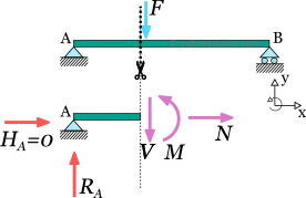
In the following figure, a section cut is illustrated at a random point of a simply supported beam. Let's select the left part to work with. The unknown internal actions, , and have been inserted at the cut, with their positive directions. For the moment, accept the shown directions as correct ones. We will elaborate on the convention for positive directions later.
Next we have to write the equilibrium equations for the left part. Apart from the internal actions , and , there are support reactions and at point A. There is no imposed load though, in the left part. The equilibrium equations, according to our axes system (see figure), are the following:
From the first equation we get , which means that no axial force occurs at the specific point. But since this point is a random one, it can be claimed that there is no axial force along the beam span. It is not hard to prove, that unless there is a horizontal component of imposed loads, the axial force in a simply supported beam is always zero.
From the second equation we get: .
And substituting to the third equation, we get: .
Point forces and point moments
Finding the shear force and the bending moment at the points where a concentrated force or bending moment is imposed, requires some more consideration. Specifically, at the location of a point load, the resulting shear force is different, to the left and the right of the application point.
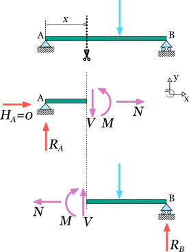
To illustrate this, let's consider the following simply supported beam. We have to determine the shear force, at the point where the imposed load is applied. So, a section cut is performed, just to the left of the application point. We also select the left part. The equilibrium of forces on axis y becomes:
We have not included the force F in the equilibrium because the cut was made to the left of the application point, thus, leaving F to the right part of the cut. Now let's make the cut a little bit to the right of the force F. We select again, the left part, but this time the force is included. The equilibrium becomes:
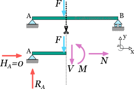
It is clear that: . It is therefore important in such cases, to clarify the side of the application point, we evaluate the transverse shear force, left or right.
Similar considerations apply when a point moment is present. To the left and right of its application point, the resulting bending moment is different.
Sign convention for bending moments and shear forces
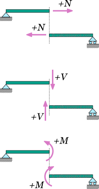
Regarding the sign convention for the internal forces and moments, at any section cut, the following conventions are usually adopted :
- The axial force is considered positive when it causes tension to the part
- The shear force is positive when it causes a clock-wise rotation of the part.
- The bending moment is positive when it causes tension to the lower fiber of the beam and compression to the top fiber.
These rules, though not mandatory, are rather established. A different set of rules, if followed consistently would also produce correct results.
Example 1: internal actions at a section cut of a simply supported beam
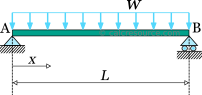
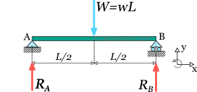
For the following simply supported beam, loaded by a uniform distributed load:
- Find the bending moment and the transverse shear force at the middle span
- Find the bending moment and the transverse shear force as a function of distance x from edge A
Support reactions
Before proceeding to find the internal forces and moments, we have to determine the support reactions for the given structure. We assume these are , at ends A and B respectively (horizontal reaction at A is zero since there is no horizontal component of imposed loading). Also we replace the distributed load with an equivalent point load, having magnitude , and applied at the middle.
The equilibrium equations are:
From the last equation we find:
And by substitution of to the first equation we find:
Finding the internal action in the middle span
Step 1. We make a cut at the middle of the beam, and we select the right part.
Step 2. We place the internal forces and moments to the cut, with their positive directions. is the bending moment, (V\) is the shear force and is the axial force. Note, that even though the calculation of is not required, and we could omit including it, in the equilibrium, without harm, in a more general case, such omission would produce wrong results.
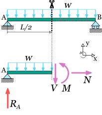
Step 3. We enforce equilibrium to the cut part. Before writing the equations, we replace the distributed load with an equivalent point load. This should have magnitude and application point in the middle of the part, that is a quarter length from end A.
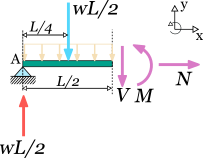
The equilibrium equations are:
Step 4. The system of equilibrium equations is solved. From the first equation we get that the axial force is zero. From the second equation we find shear force at the middle is also zero:
From the last equation we find the bending moment , after setting the values for and :
Finding the bending moment and shear force as a function of distance x
In order to find the relationship between the internal forces or moments against distance , all we have to do is a cut at that distance , from the left end. The procedure remains the same. We select the left part of the cut and we introduce the unknown quantities as for the bending moment, for the shear force and for the axial force. Also we replace the imposed to the cut part, distributed load with its equivalent point load. This should have magnitude and application point the middle of the cut part, that is located at a distance from end A.
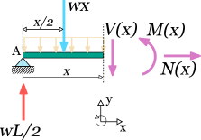
The equilibrium equations are :
From the second equation we get:
And from the third equation we find :
Bending moment diagram and shear force diagram
Knowing the internal forces and moments at a specific point is useful, but it cannot give a thorough insight what is happening in the whole structure. To gain this information, one would need to make a large number of cuts throughout the structure. Doing so, critical points in the structure could be identified, where the bending moment or the shear force or the axial force get their peak values.
In this context, it is quite helpful to illustrate how bending moments are varying inside a structure. The bending moment diagram, or BMD in short, is a diagram plotted on-top the structure, that displays the value of the bending moment at any point. Similarly the shear force diagram, or SFD, displays the value of shear force at any point of the structure while the axial force diagram, or AFD, displays the value of the axial force.
In order to construct any of these diagrams, we should preferably know the analytical expression(s) of the corresponding quantity (e.g. the bending moment for the BMD) along the structural member(s). For the simply supported beam, such analytical expressions are rather easy to calculate, as shown in the last example.
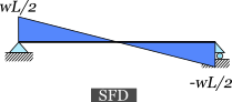
Example 2: BMD and SFD of a simply supported beam
For the simply supported beam of the previous example, construct the bending moment diagram and the shear force diagram.
From the solution of the previous example, we have found the analytical expressions of the shear force and the bending moment against distance x from the left end.
To construct the diagrams, all we have to do is plot these expressions along the beam length, from to . But first, let's examine the expressions.
is a linear function of , so it is adequate to know its value at two points, in order to plot it accurately.
- For :
- For :
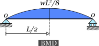
is a quadratic function of , so its curve should be parabolic. Let't find its values at the two ends first:
- For :
- For :
Also, let's, find its peak value. Its first derivative is quite simple to find:
The peak value should occur at a where the first derivative becomes zero:
This is at the middle of the beam. Then the peak value is: